




Knowledge Base
Electronic Principles, Comparing Solid State Relays (SSR) with Electromechanical Relays (EMR), and How to Choose the Right One
Electronics Principles, SSR vs EMR Comparison & Selection Guide
- What is a Solid State Relay (SSR)? Overview & Differences from Electromechanical Relays (EMR)
- Electronic Working Principles
- Types of Solid State Relays
- Comparison Table: Solid State Relay (SSR) vs Mechanical Relay
- Using a Solid State Relay (SSR) with a PID Controller
- How to Choose the Right Solid State Relay (SSR)
- Common Problems and Solutions
- Frequently Asked Questions (FAQ)
What is a Solid State Relay (SSR)? Overview & Differences from Electromechanical Relays (EMR)
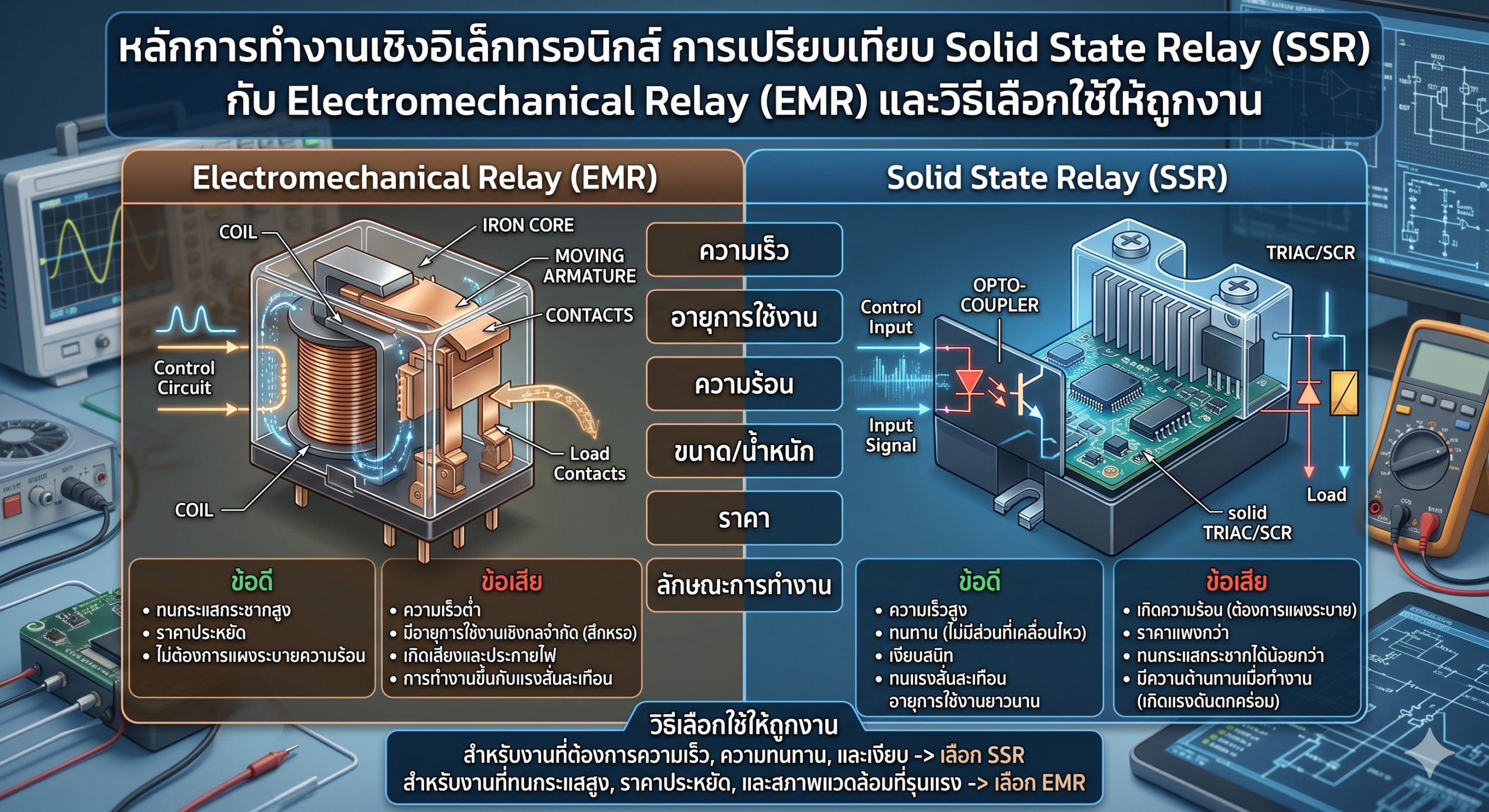
A Solid State Relay (SSR) is an electrical switching device that uses a small control signal (Input) to switch a large power circuit (Output/Load) on or off without any moving parts. Everything happens entirely within a single semiconductor component.
This is vastly different from an Electromechanical Relay (EMR)—commonly known as a Mechanical Relay—which uses a magnetic coil to physically pull metal contacts together. EMRs make noise, suffer from mechanical wear, and generate a spark every time they switch.
Electronic Working Principles
Internal Structure of a Solid State Relay (SSR)
A Solid State Relay consists of three main interconnected circuits, featuring complete electrical separation (Galvanic Isolation) between the Input and Output.
2. Optocoupler (LED + Photodetector): An internal LED lights up when the input signal is applied. This light strikes a photodetector, completely isolating the input and output circuits, providing high safety and noise immunity.
3. Switching Element (Output): The photodetector triggers a Triac (for AC Loads) or a MOSFET/SCR (for DC Loads) to conduct current, closing the load circuit.
4. Zero-Crossing Circuit: AC SSRs often include this circuit to ensure switching only occurs when the AC waveform crosses zero volts, drastically reducing EMI and voltage spikes.
Types of Solid State Relays
Categorized by the Load (Output) Controlled
Most Common
DC Applications
Industrial Use
Power Control
Categorized by Input Signal
- DC Input (3-32VDC): The most common type. Connects directly to PLC outputs, PID controllers, or timers.
- AC Input (90-280VAC): Receives an AC signal directly. Suitable for systems without a DC control voltage.
- Analog Input (4-20mA / 0-10V): Used for proportional SSRs to adjust power output linearly based on the signal.
Comparison Table: Solid State Relay (SSR) vs Electromechanical Relay (EMR)
| Feature | Solid State Relay (SSR) | Electromechanical Relay (EMR) |
|---|---|---|
| Moving Parts | ● None | ● Yes (Armature, Contacts) |
| Lifespan | ● 100 Million+ cycles | ● 100,000 – 1,000,000 cycles |
| Switching Speed | ● Extremely Fast (ms to µs) | ● Slower (5-15ms) |
| Noise & Vibration | ● Completely silent, no vibration | ● Audible clicking, vibrates |
| Spark / Arcing | ● None | ● Yes (Risky in flammable areas) |
| Heat Generation | ● High (Requires a Heatsink) | ● Low |
| Inrush Current Tolerance | ● Moderate (Careful with Motors/Capacitors) | ● Excellent |
| Input/Output Isolation | ● Complete optical isolation | ● Isolated via magnetic coil |
| Compatible Loads | Best for Resistive. Caution with Inductive. | Supports a broader variety of loads |
| Price | ● Higher | ● Lower |
| Best Suited For | Temperature control, frequent switching, quiet areas | Mixed loads, infrequent switching, tight budgets |
Using a Solid State Relay (SSR) with a PID Controller
An SSR truly shines when paired with a PID Controller in temperature control systems. Because SSRs can switch incredibly fast without mechanical wear, they can endure constant On-Off cycling without degrading.
How They Work Together
PID Controller >> Calculates the error (SP – PV) and sends an output as:
– ON/OFF Signal (Relay Output) >> To the SSR Input.
– Pulse Width Modulation (PWM) >> High-frequency SSR switching.
SSR >> Receives the signal and switches the Heater on/off matching the Duty Cycle.
Heater >> Provides heat until the Setpoint is reached.
ON/OFF Control vs PWM: Which one to choose?
Simple & Cheap
High Precision
How to Choose the Right Solid State Relay (SSR)
-
1Is the Load AC or DC?For an AC Load (e.g., 220V Heater) >> Choose an AC Output SSR. | For a DC Load (e.g., DC Motor, Solenoid) >> Choose a DC Output SSR utilizing a MOSFET.
-
2What is the maximum Load Current?Select an SSR Current Rating that is 2-3 times higher than the actual load. For example, for a 10A heater, use a 25-40A SSR. SSRs get dangerously hot when operated near their limit.
-
3What is the Input Signal from the Controller?PLC Output 24VDC >> Use a 3-32VDC Input SSR. | PID Relay Output >> Use either a 3-32VDC or 90-280VAC Input SSR, depending on the PID’s specs.
-
4What type of Load is it?Resistive (Heaters, Lamps) >> SSRs perform perfectly. | Inductive (Motors, Transformers) >> You must add an RC Snubber or specifically choose an SSR rated for inductive loads.
-
5Environment and CoolingInside a Control Panel >> Mount on a DIN Rail with a heatsink. | Hot environment or enclosed cabinet >> You must calculate thermal derating and likely install a cooling fan.
- Frequent switching (more than 10 times/minute) >> Always SSR.
- Load is a Resistive Heater controlled by a PID >> SSR is the best choice.
- Environment has flammable gases or vapors >> SSR (Spark-free, much safer).
- Load is a large motor with high Inrush Current >> EMR is more robust.
- Tight budget and infrequent switching >> EMR is cheaper and sufficient.
Common Problems and Solutions
| Problem | Cause | Solution |
|---|---|---|
| SSR gets extremely hot | Exceeding current rating or inadequate heatsink. | Reduce load, or upgrade to a higher-rated SSR. Ensure proper heatsink and thermal compound are used. |
| SSR won’t turn off completely (Load stays on) | Triac’s Off-state Leakage Current is flowing through the load. | Normal for AC SSRs. If the load is a lamp, it might flicker. Fix by wiring a Bleeder Resistor in parallel with the load. |
| SSR burns out frequently | Inrush Current from Inductive/Capacitive loads exceeded the Peak Rating. | Add an RC Snubber across the load, or choose an SSR explicitly rated for High Inrush. |
| Load turns on without an Input Signal | EMI/Noise interfering with the Input Circuit, causing false triggering. | Add an RC Filter to the input, use shielded cables, and route signal wires away from power lines. |
| SSR doesn’t turn on despite having an Input | Input Voltage is below the Minimum Turn-on threshold, or polarity is reversed. | Verify the voltage at the input terminals and ensure +/- polarity is correct. |
Frequently Asked Questions (FAQ)
Tell us your load type, current, and controller, and we’ll help you find the exact match.
