





Knowledge Base
Understanding operating principles, signal outputs, and how to choose the right instrument.
How They Work, Signal Types & Selection Guide
Overview: Two Frequently Confused Instruments
In piping systems and Process Control, two of the most frequently confused terms are Pressure Transmitter and Pressure Gauge. Both measure pressure, but they serve entirely different roles. Choosing the wrong one can stall an automation system or force engineers to run to the field every time they need a reading.
Engineering Principles
Pressure Gauge: Mechanical Mechanism
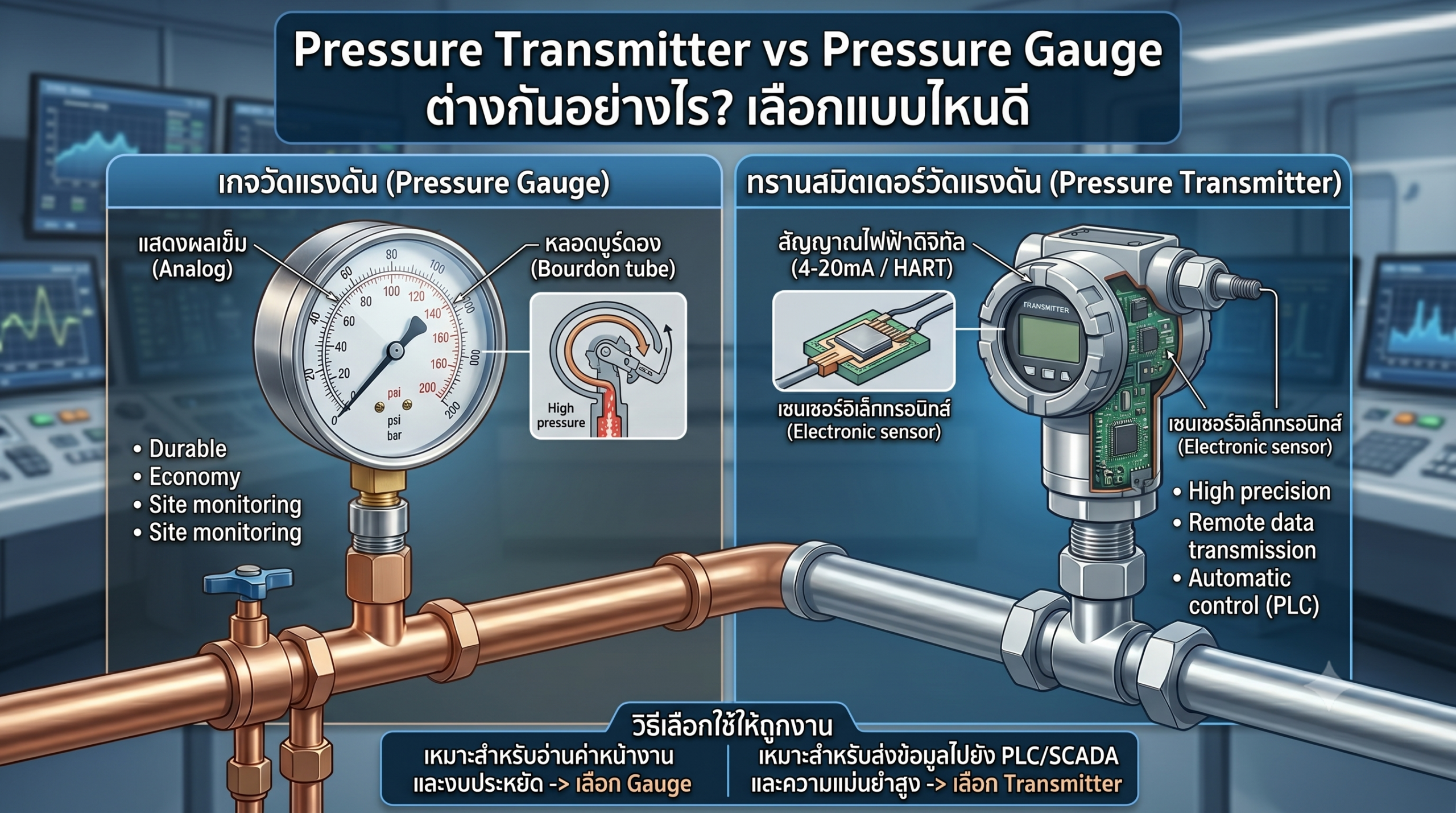
Standard Pressure Gauges typically use a Bourdon Tube, which is a C-shaped hollow metal tube. When pressurized fluid enters the tube, it attempts to straighten out proportionally to the pressure applied. This mechanical movement is transferred through a gear and linkage system to turn a pointer on the dial.
Diaphragm: Used for lower pressures or viscous/corrosive fluids.
Capsule: Used for very low pressures, such as near-zero gas pressure.
Bellows: Used for low pressure and differential pressure applications.
Pressure Transmitter: Signal Conversion
A Pressure Transmitter operates in two main steps: Sensing and Signal Conditioning. A sensing element converts the physical pressure into an intermediate physical property, which an electronic circuit then converts into a standardized electrical signal.
2. Converts to raw electrical signal: Mechanical pressure >> Changes in resistance/capacitance.
3. Signal Conditioning: Amplifies, filters, and compensates for temperature variations.
4. Output Signal: Converts the conditioned data into a 4-20mA loop or Digital Protocol.
Types of Pressure Measurements
- Gauge Pressure: Measured relative to ambient atmospheric pressure (0 = atmospheric pressure). Most common.
- Absolute Pressure: Measured relative to a perfect vacuum. Ideal for applications requiring high precision.
- Differential Pressure: Measures the difference in pressure between two distinct points. Often used to calculate flow rates.
- Vacuum Pressure: Measures pressure below standard atmospheric pressure.
Signal Outputs and PLC/SCADA Wiring
This is where the Pressure Transmitter completely departs from the Pressure Gauge. The transmitter sends data as an electrical signal that automation systems can read directly.
Types of Signal Outputs
HART Protocol
PROFIBUS
Foundation Fieldbus
IO-Link
| Signal Type | Characteristics | Advantages | Best Suited For |
|---|---|---|---|
| 4-20mA | Analog, 2-wire | Simple, noise-resistant, long-distance transmission | General applications, legacy and modern PLCs |
| HART | Digital superimposed on 4-20mA | Transmits 2 signals simultaneously, allows diagnostics | Plants requiring remote configuration |
| PROFIBUS PA | Fieldbus Digital | Connect multiple devices on a single cable | Large-scale facilities, SIEMENS architectures |
| Foundation Fieldbus | Fieldbus Digital | Can process control logic directly in the field device | Oil & Gas industry |
| IO-Link | Digital Point-to-Point | Simple, low cost, software configurable | General Factory Automation |
Wiring a Pressure Transmitter to a PLC/SCADA
Voltage drop across the Load Resistor = Current × 250Ω
At 4mA → 1.0V = 0% of Range
At 20mA → 5.0V = 100% of Range
Conversion Formula: Engineering Value = [(I – 4) ÷ 16] × (Max – Min) + Min
Example: If Current is 12mA, and Range is 0-10 bar → [(12-4) ÷ 16] × 10 = 5.0 bar
Comparison Table: Transmitter vs. Gauge
| Feature | Pressure Transmitter | Pressure Gauge |
|---|---|---|
| Output | Electrical signal (4-20mA, HART, Fieldbus) | Value displayed on a mechanical dial |
| Reading Location | ● Read remotely via PLC/SCADA | ● Must be read locally on-site |
| Accuracy | ● High: ±0.1% to ±0.5% FS | ● Moderate: ±1% to ±2.5% FS |
| Automation Integration | ● Direct integration | ● None. Requires a separate Pressure Switch |
| Data Logging | ● Automated recording in Historian/SCADA | ● Requires manual, physical recording |
| Alarm/Interlock | ● Setpoints easily configured in the PLC | ● Requires a separate Pressure Switch |
| Price | ● Higher | ● Lower |
| Maintenance Needs | Routine calibration, potential electronic failure | Foggy glass, stuck needles, ruptured Bourdon tube |
| Requires Power? | Yes (e.g., 24VDC Loop Power) | No |
| Best Suited For | Automation systems, remote monitoring | Visual verification, local indication |
How to Choose the Right Instrument
Answering these 4 simple questions will help you make an immediate decision.
-
1Does the system need to know the pressure automatically?Yes >> You must use a Pressure Transmitter. / No, only a human operator needs to see it >> A Pressure Gauge is sufficient.
-
2Do you have a PLC, DCS, or SCADA system in place?Yes >> Choose a Transmitter with a signal output matching your PLC’s AI card (e.g., 4-20mA or HART). / No >> A Gauge is much cheaper and requires no additional infrastructure.
-
3Do you need automatic Alarms or Shutdowns?Yes >> Use a Transmitter and set parameters in the PLC. / No >> A simple Pressure Switch or Gauge is enough.
-
4Do you require standard calibration or an audit trail?Yes (e.g., Pharma, Food Grade, ISO standards) >> You need a Transmitter with a Calibration Certificate. / No >> A standard Gauge is fine.
- Install a Pressure Transmitter to feed data to the PLC/SCADA.
- Install a Pressure Gauge alongside it at the same measurement point for field technicians.
- This allows instant visual verification of the Transmitter’s readings without opening the SCADA interface.
- It saves on shutdown costs for calibration since you have an immediate point of comparison.
Common Problems and Troubleshooting
Pressure Transmitter Issues
| Problem | Cause | Solution |
|---|---|---|
| Output is 0mA or 3.6mA | Wire Break or Power Supply failure. | Check the loop wiring and verify the 24VDC Power Supply. |
| Abnormal signal fluctuation | Electrical noise interference from nearby equipment. | Use Shielded Cable and ground the shield at the control panel. |
| Reading deviates from actual | Zero/Span drift after prolonged use or severe temperature changes. | Perform routine calibration every 6 to 12 months. |
| HART is not responding | Incorrect Load Resistance (requires 230-500Ω). | Verify that the total Loop Resistance falls within the acceptable range. |
Pressure Gauge Issues
| Problem | Cause | Solution |
|---|---|---|
| Needle is stuck/unresponsive | Clogged Bourdon Tube or worn-out gear mechanisms. | Clean the tube or replace the mechanical movement assembly. |
| Foggy or opaque glass | Moisture entered the case due to degraded seals. | Replace the case seals or upgrade to an IP66-rated model or higher. |
| Needle vibrating constantly | System has severe pressure pulsation or high vibration. | Install a Snubber or switch to a Glycerin-filled pressure gauge. |
| Inaccurate readings | Incorrect installation orientation or misaligned Zero point. | Ensure perpendicular installation and adjust the Zero screw. |
Frequently Asked Questions (FAQ)
Tell us about your PLC system, media type, and pressure range, and we will help you find the exact match.
